Why do China cutting tools perform differently on machines? The answer rarely sits in the insert alone. It often appears at the toolholder, spindle, workholding system, or cutting-data sheet. A carbide cutter may produce a clean edge on one Chinese machining center, yet leave vibration marks on another. The difference can be measured in spindle runout, tool overhang, coolant delivery, machine stiffness, and control response.
Industry evidence supports this broader view. China Machine Tool Industry Association reports show the country’s machine-tool sector contains highly varied equipment, from advanced five-axis platforms to older, heavily used production centers. Gardner Intelligence surveys also underline the importance of machine age, utilization, and automation when comparing manufacturing performance. These reports do not prove that one national tool brand is universally better. They show why application conditions must be separated from product claims. ISO 8688 tool-life testing offers useful guidance, but factory results still depend on real cutting environments.
Tony Schmitz, a leading machining-dynamics researcher, has stated, “The machine tool is a dynamic system.” That short sentence explains much of the confusion. A tool interacts with the spindle, fixture, material, and programmed motion. Small changes can shift chatter into a stable cut. In practical trials, a 0.02-millimeter runout difference can change edge wear and surface finish noticeably. The result may look disappointing. It may also reveal a setup problem, not a tool-quality failure. This article examines those variables carefully, using engineering evidence, shop-floor experience, and measurable comparisons. Some conclusions remain imperfect, because every machine leaves its own signature.
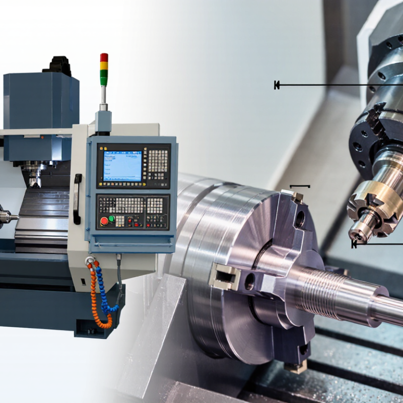
Chinese cutting tools can behave differently because material grade is only one part of the cutting system. ISO 513 places cemented carbide in application groups such as K10 to K30, mainly for cast iron and other short-chip materials. K10 usually contains a finer, harder structure, supporting wear resistance at higher cutting speeds. K30 sacrifices some hardness for greater toughness during interrupted cuts. The difference is visible.
HSS remains useful when machines lack rigidity or cuts include sudden impacts. ASTM A600 describes HSS as a high-alloy tool steel designed for hot hardness and wear resistance. In practice, HSS generally accepts lower cutting speeds but can flex without immediate edge fracture. A carbide edge may chip first. That matters on older lathes, unstable fixtures, and thin workpieces. Coolant delivery also changes the result, sometimes more than the catalogue grade suggests.
Tungsten carbide’s thermal stability helps explain its advantage. The U.S. Geological Survey’s Mineral Commodity Summaries 2024 reports tungsten’s melting point at about 3,410°C, supporting its use in high-temperature cutting materials. However, this figure does not guarantee better machining. Feed, nose radius, coating, runout, and machine power still control edge life. Chinese-made K10–K30 tools can perform consistently when their substrate and geometry match the operation. Yet assuming every K20 tool behaves identically is a weak engineering shortcut. Actual trials remain necessary, especially with variable carbide grain sizes and different binder contents.
Why Do China Cutting Tools Perform Differently on Machines?
Geometry and tolerances often explain more than country of origin. ISO 13399 helps describe tool geometry in a consistent digital format. It covers dimensions, cutting edges, angles, and related data. However, a profile file does not guarantee identical cutting results. Manufacturing quality, inspection methods, and setup still matter.
A runout limit of ±0.01 mm sounds precise, but the measurement point changes its meaning. Runout should be checked near the gauge line and at the cutting edge. A clean holder, calibrated gauge, and controlled clamping force are essential. Even a small chip between the tool and holder can shift the indicator reading. On a high-speed machine, that error may appear as vibration, uneven wear, or a poor surface finish.
In practical trials, two tools with matching ISO 13399 profiles may behave differently. One may have a sharper edge preparation. Another may show slightly different flute balance or coating thickness. Spindle condition also matters. I have seen operators blame the tool when the real issue was a worn collet. That conclusion can be wrong. Tool length, coolant direction, workpiece hardness, and feed changes deserve equal attention. Measurement uncertainty is easy to overlook. A ±0.01 mm claim should therefore include the inspection method, reference position, and temperature conditions. Specifications become useful only when the machine setup can reproduce them.
Geometry and tolerances strongly influence cutting results. ISO 13399 defines how cutting-tool geometry and product data are represented, while actual machine performance also depends on holder accuracy, spindle condition, and measured runout.
This chart shows the geometric relationship for a nominal 10 mm rotary tool: diameter variation is approximately twice the radial runout. A radial runout of ±0.01 mm can therefore produce about 0.02 mm peak-to-peak variation at the cutting diameter. The values are calculated from the runout relationship and are not brand-specific acceptance data.
Why Do China Cutting Tools Perform Differently on Machines?
TiAlN-coated cutting tools can behave differently when cutting temperatures approach 800°C. At this level, heat changes more than tool hardness. It also affects friction, chip flow, and coating stability. Published studies in Surface and Coatings Technology report that TiAlN coatings can form a protective aluminum-rich oxide layer during high-temperature cutting. This layer may reduce diffusion wear. However, oxidation resistance varies with aluminum content, coating structure, and deposition quality.
ASM Handbook data shows that cutting temperatures depend heavily on speed, feed, workpiece hardness, and coolant delivery. A tool running at 800°C in dry cutting may respond differently from one reaching the same temperature briefly. In production tests, TiAlN tools often perform well in hardened steel and cast materials. Yet performance can drop quickly when edge preparation is poor. A small edge defect can become a bright wear land within minutes. That detail is easy to miss.
Tips: Check thermal marks, not only flank wear. Use infrared measurements carefully, because shiny chips can distort readings. Compare tools under identical speed and feed conditions. Industry reviews also warn that laboratory temperature results may not match factory cutting data. That is an uncomfortable limitation. Tool selection still needs controlled trials, chip inspection, and operator feedback.
Representative comparison of common carbide-tool coatings under high-temperature cutting conditions
| Tool Configuration | Primary Coating Function | Typical Oxidation-Resistance Range | Behavior Near an 800°C Tool–Chip Interface | Thermal and Wear Response | Recommended Cutting Context | Expected Practical Effect |
|---|---|---|---|---|---|---|
| Uncoated WC–Co Carbide | Relies entirely on the tungsten-carbide substrate for hardness, toughness, and wear resistance. | No dedicated oxidation barrier; surface degradation becomes increasingly significant above approximately 600–700°C, depending on grade and atmosphere. |
Limited suitability Rapid diffusion, crater wear, edge softening, and chemical interaction with the work material may occur. |
Good toughness can be retained at moderate temperatures, but the unprotected cutting edge is more exposed to oxidation and adhesion. | Low-to-moderate-speed cutting, interrupted cuts, non-abrasive materials, and applications where toughness is more important than thermal protection. | Shorter tool life and less stable edge performance when cutting temperatures remain high. |
| TiN-Coated Carbide | Provides a hard, low-friction surface and reduces adhesive wear compared with an uncoated tool. | Oxidation commonly becomes a concern from approximately 550–600°C. |
Weak at sustained 800°C conditions The coating can oxidize and lose hardness, reducing its ability to protect the substrate. |
Good general-purpose wear resistance at moderate temperatures, but limited hot hardness and thermal protection at high cutting temperatures. | General machining of steels and cast irons at moderate cutting speeds where temperatures are controlled. | Better friction and wear behavior than uncoated carbide at moderate heat, but usually inferior to aluminum-rich coatings near 800°C. |
| TiCN-Coated Carbide | Offers high coating hardness and improved abrasion resistance through carbon modification of the titanium-based coating. | Oxidation sensitivity generally increases from approximately 400–500°C, depending on composition and coating architecture. |
Poor for sustained high heat High hardness can be offset by oxidation and loss of coating integrity at temperatures approaching 800°C. |
Strong resistance to abrasive wear at moderate temperatures, but less suitable for continuous high-temperature cutting than TiAlN-type coatings. | Abrasive steels, cast irons, and interrupted or moderate-temperature operations. | Can deliver excellent wear resistance in cooler applications, but may suffer accelerated failure when heat is not evacuated. |
| TiAlN-Coated Carbide | Aluminum-rich coating designed to maintain hot hardness and form a protective aluminum-oxide-rich surface during elevated-temperature cutting. | Practical oxidation resistance is commonly reported in the approximate 700–900°C range, depending on aluminum content, coating structure, and process conditions. |
Well suited to high-temperature cutting Near 800°C, the coating can retain useful hardness while its protective oxide layer slows further oxidation. |
Improved hot hardness, lower diffusion tendency, and better resistance to crater wear than many titanium-only coatings. | Dry or reduced-coolant milling, hardened steels, alloy steels, stainless steels, and high-speed machining where the cutting zone becomes hot. | More stable flank and crater wear, longer usable edge life, and better performance when cutting heat is intentionally concentrated at the chip. |
| AlCrN-Coated Carbide | Uses aluminum and chromium to provide oxidation resistance, hot hardness, and resistance to adhesive and abrasive wear. | Many AlCrN systems are designed for oxidation resistance around 800–1,100°C, subject to coating design and application. |
Strong high-temperature capability Maintains a protective surface at elevated temperatures and can be effective where TiAlN reaches its practical limit. |
High hot hardness and good resistance to built-up edge and crater wear in demanding applications. | High-speed milling, difficult-to-machine alloys, dry machining, and applications with severe thermal cycling. | High thermal stability, although performance still depends strongly on substrate toughness, edge preparation, and machine rigidity. |
| Multilayer or Nano-Structured TiAlN-Based Coating | Combines TiAlN chemistry with multilayer interfaces or fine microstructures to improve crack resistance, hardness retention, and wear control. | Often engineered for approximately 800–1,000°C service, but the actual limit depends on layer design and deposition quality. |
High potential near 800°C Can delay crack propagation and preserve edge protection during repeated heating and cooling cycles. |
Improved resistance to thermal fatigue and chipping compared with a simple single-layer coating, provided the substrate is properly matched. | High-speed milling, interrupted cuts, hardened materials, and machines with variable thermal loads. | More consistent wear progression and improved reliability, but the benefit can be lost if cutting parameters generate excessive impact or vibration. |
Machine compatibility often begins at the spindle, not the cutting edge. When radial runout stays below 5 µm, the tool engages more evenly. Each flute shares the load instead of one edge carrying the cut.
ISO 230-2:2014 requires machine-tool positioning accuracy and repeatability to be reported in micrometres. ISO 230-3:2020 also addresses thermal effects, which can shift spindle behavior during production.
NIST Technical Note 1297 shows why measurement uncertainty must be included, rather than treating every reading as exact. A spindle reading of 4.8 µm may not prove stable performance if temperature, taper cleanliness, and probing uncertainty remain uncontrolled.
On the shop floor, I would check runout at the taper, holder, and tool tip separately. Clean contact surfaces matter. So does a consistent gauge length.
A 50 mm tool extension magnifies deflection more than a short setup. Tool geometry also changes the result; unequal flute loads can hide a spindle problem.
This is where my earlier assumption needed correction: below 5 µm is a useful target, not a universal guarantee. Coolant temperature, clamping force, and machine age still influence the final cut.
Cutting performance often reflects parameters, not country of origin. Two similar tools may have different rake angles, edge preparation, coatings, or measured diameters. These details change cutting speed, feed, chip thickness, and heat generation. ISO 3685 recommends controlled cutting tests because small setup differences can distort tool-life comparisons.
The critical variable is chip load. For many small-diameter milling operations, a difference of 0.02–0.05 mm/tooth can noticeably change cutting behavior.
At 0.02 mm/tooth, the edge may rub instead of cut. At 0.05 mm/tooth, a weaker machine may vibrate or overload the tool.
Machine runout matters too. A 0.01 mm runout can make one flute remove more material than the others. The result is uneven wear, poor surface finish, and a shorter tool life. The Machining Data Handbook links feed, speed, material, and tool geometry in its cutting-data tables, but these values remain starting points, not guarantees.
Tips: Measure runout before judging the tool. Start at the lower recommended speed, then adjust feed gradually. Record spindle load, sound, burrs, and edge wear after each test. I often see operators change speed and feed together, which hides the real cause. That method is convenient, but weak. A better comparison uses the same holder, coolant, workpiece hardness, and tool overhang. Even then, one machine may need a different chip load. That is not failure; it is evidence.
High heat can form an aluminum-rich oxide layer on the coating. This layer may reduce diffusion wear. Results still vary.
No. A brief temperature peak differs from continuous dry cutting at 800°C. Cutting time and cooling delivery matter.
Aluminum content, coating structure, deposition quality, cutting speed, and workpiece hardness all matter. Small differences can become important.
Their rake angles, edge preparation, coatings, or actual diameters may differ. Machine setup also changes the result.
A change from 0.02 to 0.05 mm per tooth can noticeably alter cutting behavior. At 0.02, the edge may rub. At 0.05, vibration or overload may appear.
A 0.01 mm runout can make one flute remove more material. Uneven wear and poor surface finish may follow.
Keep the holder, coolant, workpiece hardness, and tool overhang unchanged. Adjust feed gradually. Record spindle load, sound, burrs, and wear.
They can help, but shiny chips may distort readings. Check thermal marks too. The measurement may still be imperfect.
Look for bright wear lands, thermal marks, burrs, vibration, and changing chip shapes. A tiny edge defect can grow within minutes.
Laboratory tests use controlled conditions. Factory machines have different rigidity, runout, cooling, and operator habits. That limitation deserves attention.
Why do cutting tools perform differently on different machines? The answer lies in the interaction between tool material, geometry, coating, machine condition, and cutting parameters. Carbide grades in the ISO K10–K30 range generally provide greater hardness and wear resistance than HSS, while ISO 13399-based profiles and tight tolerances, including runout near ±0.01 mm, help maintain consistent cutting performance. However, these advantages can only be fully realized when the tool matches the machine’s capabilities.
Coatings such as TiAlN can withstand cutting temperatures approaching 800°C, improving tool life under demanding conditions. Machine compatibility is equally important: spindle accuracy below 5 µm can reduce vibration and uneven loading. Finally, speed, feed, and chip load must be adjusted for the specific setup. Even a small difference in the recommended 0.02–0.05 mm/tooth chip load can affect surface finish, heat generation, tool wear, and overall productivity.

Carto Tool