How to Prevent Tool Breakage in CNC Milling?

Time:2026-10-12 Author:Sienna
0%

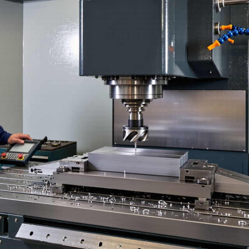
Tool breakage can turn a clean CNC milling operation into an expensive interruption. A sharp cutter may snap within seconds, leaving a chipped edge, damaged workpiece, and scattered carbide fragments inside the enclosure. Understanding what causes tool breakage in CNC milling requires more than checking cutting speed charts. It demands attention to machine behavior, material response, tool geometry, and operator decisions.

Machining researcher Dr. Tony Schmitz puts the principle plainly: “Stable cutting is the foundation of predictable tool life.” His view reflects a practical reality. Excessive radial engagement can overload the cutting edge. A loose workholding setup can create vibration marks and sudden impact. Incorrect feed rates may rub the tool instead of cutting efficiently. Coolant aimed at the wrong location can also produce uneven thermal stress. Small details matter.

Watch the sound.

An experienced operator listens for chatter before the tool fails. They inspect flute wear, confirm tool runout, and measure the stick-out length before cutting. Yet no process is perfect. Even a carefully prepared setup may break a tool when material hardness changes unexpectedly. That possibility deserves honest attention.

Reliable prevention combines documented cutting data with real shop-floor observation. Start with conservative parameters, secure the workpiece firmly, and reduce unnecessary tool overhang. Check spindle condition, collet cleanliness, and chip evacuation regularly. A broken tool should not be treated only as bad luck. Its fracture pattern may reveal vibration, overload, poor cooling, or an incorrect machining strategy. Learning from that evidence is often the most valuable preventive step.

How to Prevent Tool Breakage in CNC Milling?

Understanding the Main Causes of Tool Breakage in CNC Milling

How to Prevent Tool Breakage in CNC Milling?

Understanding the Main Causes of Tool Breakage in CNC Milling

Tool breakage usually begins with a small process imbalance. Excessive cutting force, poor chip evacuation, and unstable workholding are common triggers. A review in CIRP Journal of Manufacturing Science and Technology links sudden failure to mechanical overload, thermal fatigue, and vibration. These mechanisms often work together. A tool may survive one mistake, then fail after repeated impact.

Cutting data matters. The U.S. National Institute of Standards and Technology identifies tool-condition monitoring as essential for reducing unexpected machining interruptions. ISO 8688-2 also recommends controlled tool-life tests under defined cutting conditions. In practice, a dull edge creates more heat and force. Long chips can wrap around the cutter. A loose fixture can turn mild chatter into a sharp удар. Check runout before blaming the insert. Even 0.02 mm of radial runout can overload one cutting edge, especially during high-speed milling.

Material changes deserve attention. Hardened steel, interrupted cuts, and thin walls demand different load strategies. Reduce radial engagement when chatter appears, but do not lower feed blindly. That choice may create rubbing instead of cutting. I have seen operators replace tools repeatedly while ignoring coolant direction and chip packing. The tool was not always the main problem. Record spindle load, vibration, tool life, and surface condition after each failure. Patterns become clearer, although the first diagnosis is sometimes wrong.

How to Prevent Tool Breakage in CNC Milling? - Understanding the Main Causes of Tool Breakage in CNC Milling
Breakage Cause Typical Mechanism Common Warning Signs Risk Level Practical Prevention Measures Key Checks or Metrics
Excessive cutting force Cutting speed, feed rate, axial depth, or radial engagement is too high for the tool, material, or machine rigidity. Spindle-load spikes, chatter, poor surface finish, tool deflection, or sudden tool failure. High Use manufacturer-recommended starting parameters, reduce radial engagement in difficult cuts, and increase cutting conditions gradually after verifying stability. Spindle load and chip thickness; compare actual load with the machine’s normal range.
Incorrect feed and speed combination Low feed can cause rubbing and heat, while excessive feed can overload the cutting edges and increase chip thickness beyond the tool’s capability. Discolored tool edges, built-up material, squealing, oversized features, or chipped corners. High Calculate feed per tooth from spindle speed and tooth count. Adjust feed and speed according to workpiece material, tool diameter, flute count, and engagement. Feed per tooth and cutting speed; verify programmed values against the tool setup sheet.
Insufficient or unsuitable coolant Inadequate cooling or chip evacuation causes excessive heat, thermal fatigue, chip recutting, or material welding to the tool. Smoke, blue or dark tool marks, built-up edge, chip packing, and unstable cutting noise. High Aim coolant directly at the cutting zone, maintain sufficient flow and concentration, and use air or through-tool coolant where chip evacuation is critical. Coolant concentration, flow, and direction; inspect nozzles and filters routinely.
Poor chip evacuation Chips remain in the cutting zone and are recut, increasing heat and impact loading on the tool. Packed flutes, scratches on the machined surface, rising spindle load, and intermittent tool noise. High Use suitable flute geometry, adequate flute space, air blast or coolant, and toolpaths that avoid trapping chips in pockets and deep cavities. Chip shape and flute condition; stop the process if chips become long, welded, or densely packed.
Tool runout or improper toolholding Uneven radial loading causes one or more flutes to remove most of the material, accelerating wear and chipping. Uneven flute wear, vibration, poor finish, dimensional variation, or premature failure at low programmed loads. High Clean the holder and tool shank, use the correct holder size, tighten according to procedure, minimize tool overhang, and measure runout during setup. Tool-tip runout; precision cutting setups commonly require runout to be kept within a few micrometres, depending on the operation.
Excessive tool overhang A long unsupported tool behaves like a flexible beam, reducing rigidity and increasing deflection and vibration. Chatter marks, tapered walls, dimensional error, corner chipping, and unstable sound during entry or heavy cuts. High Use the shortest practical tool, select a rigid holder, reduce radial and axial engagement when necessary, and lower cutting force for deep-reach work. Stick-out-to-diameter ratio; reduce stick-out whenever tool access permits.
Workpiece movement or weak fixturing Insufficient clamping or thin-section deformation allows the workpiece to move, causing impact loads and interrupted cutting. Visible part movement, changing dimensions, vibration, burrs, and tool damage concentrated at entry or exit points. High Improve support under thin sections, place clamps close to the cutting area without obstructing the toolpath, and confirm clamping before machining. Part stability and dimensional repeatability; verify the setup after roughing and before finishing.
Interrupted cuts and sudden engagement Entering a slot, open cavity, hard scale, hole, or irregular surface creates repeated impact loading on the cutting edges. Edge chipping, impact marks, abrupt load changes, and breakage at the start of engagement. Medium Use ramping or helical entry, control the angle of engagement, reduce feed during entry, and choose a tool geometry suitable for interrupted cuts. Entry feed and engagement angle; monitor the first contact between tool and material.
Worn, damaged, or unsuitable tool Wear reduces edge strength and increases cutting force; an unsuitable coating, geometry, or substrate may fail under the application’s thermal and mechanical conditions. Flank wear, crater wear, edge rounding, chipping, higher spindle load, and worsening surface finish. High Set tool-life limits, inspect edges at planned intervals, use tooling matched to the workpiece, and replace tools before catastrophic failure. Flank-wear land, edge condition, and load trend; record tool life by operation and material.
Machine or spindle vibration Low machine rigidity, bearing issues, loose components, or an unstable toolpath amplifies cutting forces and cyclically fatigues the tool. Periodic chatter marks, fluctuating sound, visible vibration, inconsistent finish, and repeated edge chipping. Medium Check machine condition, tighten fixtures, balance rotating assemblies when applicable, alter spindle speed, and select a more stable toolpath. Vibration pattern and surface wavelength; compare results after small speed or engagement changes.
Programming or tool-offset error Incorrect tool length, diameter compensation, work offset, coordinate, or depth causes an unintended collision or excessive engagement. Immediate overload, collision marks, unexpected depth, broken tool at program start, or incorrect part position. High Simulate the program, verify offsets and tool identity, use single-block or reduced rapid speed for first runs, and confirm safe clearance planes. Tool offset, work offset, and clearance verification; perform a documented first-piece check.
Improper tool entry and exit strategy Plunging directly into solid material or exiting with a sudden full-width cut creates a localized force peak. Breakage at the tool tip, chipped corners, entry marks, and a sharp spindle-load spike at the beginning or end of a pass. Medium Use ramp, helical, or pre-drilled entry methods; apply lead-in and lead-out moves; and avoid abrupt full-width engagement. Entry angle, ramp angle, and load spike; inspect the first and last millimetres of each toolpath.
Best practice: establish a stable baseline with conservative parameters, then optimize one variable at a time while recording tool life, spindle load, surface finish, dimensional accuracy, and chip condition.

Selecting Cutting Tools for Material, Geometry, and Machining Conditions

How to Prevent Tool Breakage in CNC Milling?

Selecting Cutting Tools for Material, Geometry, and Machining Conditions

Tool selection should begin with the workpiece, not the machine catalog. Aluminum usually benefits from sharp edges, polished flutes, and generous chip space. Stainless steel needs a tougher edge and controlled heat removal. Hardened steel often requires fine-grain carbide, suitable edge preparation, and stable cutting parameters. Match the tool to the material’s hardness, abrasiveness, and tendency to form built-up edges.

Geometry matters just as much. A variable helix can reduce vibration during long side cuts. Fewer flutes may improve chip evacuation in soft materials. More flutes can support higher feed rates when chip space remains adequate. Avoid excessive tool stickout. A slender tool can deflect, even when the programmed load seems modest. Small details matter.

Machining conditions can defeat a good tool choice. Check spindle speed, feed per tooth, radial engagement, axial depth, coolant flow, and workholding rigidity. Watch the chips. Powder suggests rubbing, while blue chips may indicate excessive heat. In shop trials, I have found that conservative settings protect tools, but they can also waste time. My first calculation is not always right. Material batches vary, and a setup may need adjustment after the first pass. Record the result, inspect the edge, and refine one variable at a time.

Setting Stable Speeds, Feeds, Depths, and Cutting Engagement

How to Prevent Tool Breakage in CNC Milling?

Stable cutting begins with matching spindle speed and feed rate to the tool, material, and cutter diameter. A practical feed calculation is teeth multiplied by chip load and RPM. This prevents rubbing, which creates heat and dulls the cutting edge. Small changes matter. Check the manufacturer’s cutting data, then reduce it when the machine, setup, or workholding feels less rigid. A sharp, secure tool should produce consistent chips, not powder or long glowing strands.

Depth of cut and radial engagement also control tool stress. Heavy axial depth with full-width engagement can overload a small cutter quickly. Try a moderate depth and a lower radial step-over when machining hard material. Keep the tool engaged smoothly, especially near corners. Sudden direction changes can cause impact loads. Watch the sound. A steady cutting tone is useful evidence, while squealing often signals excessive speed, poor chip evacuation, or insufficient feed.

Coolant or air should clear chips from the cut instead of forcing them back into the toolpath. Inspect the edge after several passes, not only after failure. I have found that conservative settings often improve consistency, although they may reduce productivity. That trade-off deserves review. A rigid workholding setup can justify higher engagement, but an uncertain setup should not. Record actual results, including chip appearance, surface finish, tool wear, and cutting temperature. These observations make future speed, feed, depth, and engagement adjustments more reliable.

Managing Workholding, Tool Runout, Coolant, and Chip Evacuation

Tool breakage in CNC milling often begins before the spindle starts. Workholding must resist cutting force without crushing the part. The U.S. National Institute of Standards and Technology reports that fixture stiffness strongly affects machining accuracy and vibration control. In practice, check jaw contact, clamping pressure, and unsupported overhangs. A thin plate may look secure, yet flex visibly near the cutter. That small movement can overload one flute.

Tool runout deserves a dial indicator, not guesswork. A 2022 review in the International Journal of Advanced Manufacturing Technology found that radial runout creates uneven tooth loading and accelerates wear. Keep total indicated runout near 0.01 mm when finishing with small tools. Recheck after cleaning the holder and collet. I have seen clean-looking assemblies fail this simple test.

Coolant and chip evacuation complete the system. The U.S. Environmental Protection Agency’s metalworking-fluid guidance identifies fluid contamination and poor maintenance as major process risks. Use a steady, correctly aimed stream, then inspect concentration and filtration routinely. Chips packed inside a deep pocket can recut the tool within seconds. Research reported in CIRP Journal of Manufacturing Science and Technology links inadequate evacuation with higher cutting temperatures and unstable forces. Air alone is sometimes insufficient. My own cautious preference is to reduce radial engagement before increasing feed, although every material demands verification. Listen for a dull, repeating impact; it may be the first warning, not an acceptable sound.

Inspecting Tool Wear and Improving the Milling Process Systematically

Tool breakage rarely begins with a loud crack. It often starts as a small change in sound, finish, or chip shape. An experienced machinist checks the tool before blaming the cutting program. Under bright light, inspect the edge for flank wear, chipping, built-up material, and discoloration. Measure critical edges with a microscope or consistent visual gauge. Record diameter loss, cutting time, material, coolant condition, and machine position. This evidence makes adjustments less subjective. Some shops skip the log. That is a costly habit.

A systematic process links wear to specific conditions. Compare tool life across feed rate, spindle speed, radial engagement, axial depth, and workholding stability. Change one variable at a time when possible. If two variables change together, the result becomes difficult to trust. Listen for intermittent vibration, especially during corners and deep pockets. Check runout at the holder, not only at the spindle. Even a small offset can overload one flute. Verify coolant flow and chip evacuation near the cutting zone. Packed chips can turn a stable cut into sudden failure.

After inspection, set practical wear limits before production begins. Replace the tool when edge damage approaches the limit, not after breakage. Use a sample part to confirm surface finish, dimensions, burrs, and heat marks. Review the data weekly with operators and programmers. My own first adjustment is not always correct. Sometimes lowering speed only hides poor chip evacuation. That mistake deserves documentation. Controlled trials and honest records gradually build a safer milling system.

FAQS

How should spindle speed and feed rate be matched?

Match them to the cutter diameter, tool material, and workpiece material. Feed rate equals tooth count multiplied by chip load and spindle speed. Too little feed can cause rubbing, heat, and dull edges. Check cutting data, then reduce it for flexible setups.

What chip appearance indicates stable cutting?

Consistent chips usually suggest balanced cutting conditions. Powder can indicate rubbing or poor engagement. Long, glowing strands may show excessive heat. Watch the chips.

How do cutting depth and radial engagement affect tool breakage?

Heavy axial depth combined with full-width engagement can overload small cutters. Use moderate depth and lower radial step-over for hard materials. Reduce engagement near corners. Sudden direction changes create impact loads.

What does an unusual cutting sound mean?

A steady cutting tone is useful evidence of stability. Squealing may indicate excessive speed, poor chip evacuation, or insufficient feed. A dull, repeating impact deserves attention. It is a warning, not a normal sound.

How can workholding prevent tool failure?

Workholding must resist cutting forces without crushing the part. Check jaw contact, clamping pressure, and unsupported overhangs. A thin plate may flex visibly near the cutter. That movement can overload one flute.

Why is tool runout important?

Runout causes uneven tooth loading and faster wear. Check it with a dial indicator instead of guessing. For small finishing tools, keep total indicated runout near 0.01 mm. Clean the holder and collet, then measure again.

How should coolant and air be used?

Aim coolant or air toward the cutting zone and chip exit. Do not force chips back into the toolpath. Check fluid concentration and filtration routinely. Air alone may not clear deep pockets.

What should be recorded after machining?

Record chip appearance, surface finish, tool wear, and cutting temperature. Inspect the cutting edge after several passes. Conservative settings often improve consistency but reduce productivity. I may still choose them when the setup feels uncertain.

Conclusion

Preventing tool breakage in CNC milling starts with understanding what causes tool breakage in CNC milling, including excessive cutting forces, unsuitable tool geometry, incorrect speeds and feeds, excessive cutting depth, poor workholding, tool runout, and inadequate chip evacuation. Selecting a tool that matches the workpiece material, machining operation, and required geometry helps maintain stable cutting performance and reduce unnecessary stress.

A reliable milling process also depends on balanced cutting conditions and secure setup practices. Operators should adjust spindle speed, feed rate, axial and radial engagement, and coolant delivery according to the material and tool requirements. Proper clamping, accurate tool measurement, and effective chip removal further improve stability. Regularly inspecting cutting edges for wear, vibration marks, overheating, or deflection allows problems to be corrected before failure occurs. By reviewing tool life, machine behavior, setup accuracy, and cutting results systematically, manufacturers can reduce breakage, improve surface quality, and achieve more consistent production.

Sienna

Sienna

Sienna is a skilled marketing professional with a deep expertise in our company’s core products and services. With a passion for innovation and detail, she plays a pivotal role in crafting insightful blog posts that not only highlight the unique features of our offerings but also provide valuable......