Stainless steel can punish a cutting edge quickly. Its low thermal conductivity keeps more heat near the tool, while austenitic grades can work-harden under pressure. Outokumpu’s Core 304/430 datasheet lists 304L thermal conductivity at about 15 W/m·K near room temperature; the exact value varies with grade and temperature. In the cut, that heat can soften the edge, accelerate flank wear, and leave a bright, hardened surface for the next pass. Small details matter: a rubbing insert, a blunt corner, or a chip trapped against the workpiece.
So, how to reduce tool wear in stainless steel cutting? The answer is not simply to lower speed. Sandvik Coromant’s stainless-steel machining guidance stresses choosing suitable grades and geometries, maintaining a steady feed, and avoiding dwell or interrupted contact. E. O. Ezugwu, a researcher in machining difficult-to-cut alloys, discusses the role of cutting conditions, tool materials, and cooling in controlling tool wear. A careful paraphrase of that work is: “Manage heat and cutting conditions together; no single adjustment solves tool wear.” This is a paraphrase, not a verbatim quotation.
Start with a sharp, tough insert and a rigid setup. Keep the tool moving through the cut. Use coolant consistently when the operation and tooling call for it. Watch the chip color, edge chipping, and finish—not just the machine’s tool-life counter. One caution: a longer-lasting tool is not always the cheapest option if the cycle time rises sharply. The best setting must be tested on the actual grade, part geometry, and machine.
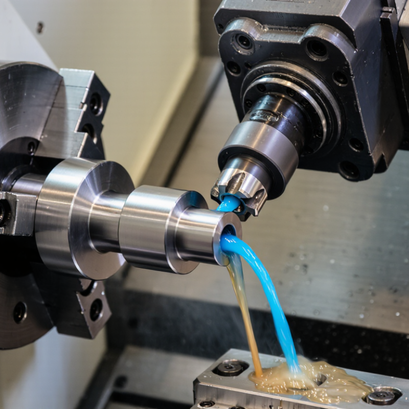
Stainless steel can wear cutting tools quickly because it combines strength with low thermal conductivity. Heat tends to stay near the cutting edge instead of leaving with the chips. Austenitic grades can also work-harden: if the tool rubs rather than cuts, the surface becomes harder for the next pass. Too little feed may cause exactly that. Adhesion is another cause. Small pieces of stainless steel can stick to the edge, then break away and pull tool material with them. The edge may look chipped.
Tips: Check the worn edge and the chips, not just the finished surface. A shiny, smeared edge can indicate adhesion; steady flank wear may point to abrasion or excessive cutting speed. Use a sharp, suitable tool, keep it cutting rather than rubbing, and direct coolant consistently when the setup allows.
Chip shape matters, too. Long, tangled chips can recut against the tool and workpiece, adding heat and damage. Adjust speed and feed gradually, then inspect wear after a short run. A lower speed is not always the answer; it can encourage rubbing if the feed is also too light. I’ve seen settings that looked cautious produce worse wear. That is a useful reminder: diagnose the failure before changing several variables at once.
Stainless steel can wear a tool quickly when heat and friction build at the cutting edge. Select a tough, fine-grain carbide grade with a coating intended for stainless machining; the best choice still depends on the alloy, machine rigidity, and coolant. ASM Handbook material-property data place Type 304 stainless steel’s thermal conductivity near 16 W/m·K at room temperature. That limited heat transfer helps explain why the tool-chip contact zone can become hot. Keep the edge sharp. A blunt edge rubs, raises heat, and can worsen work hardening.
Use a moderately positive rake, a polished rake face, and a small, controlled edge hone. Positive geometry can lower cutting forces, while an overly fragile edge may chip under vibration or interrupted cuts. There is a trade-off. Start with the tool maker’s recommended geometry and cutting conditions, then adjust using chip shape, surface finish, and wear marks. I would not assume one setup suits every stainless grade; even a small change in feed can alter the result.
Tips: Avoid dwelling at the cut. Use steady feed, direct coolant to the cutting zone, and inspect the edge after the first few parts.
Source: ASM Handbook, Volume 1, Properties and Selection: Irons, Steels, and High-Performance Alloys.
What Is the Best Way to Reduce Tool Wear in Stainless Steel?
Set Cutting Speed, Feed, and Depth of Cut
In stainless steel, heat and work hardening can wear an edge quickly. Set cutting speed within the tool maker’s recommended range, then adjust based on chips and edge condition. If the edge shows heat discoloration or built-up material, try reducing speed modestly. Watch for rubbing, too. A feed that is too low can make the tool polish the surface instead of cutting, hardening the material ahead of the next pass. Small changes help reveal what is happening.
Tips: Keep the depth of cut steady when possible. A consistent cut avoids repeatedly engaging the hardened surface left by a previous pass. Use an appropriate coolant flow to carry heat and chips away from the cutting zone. Check the insert after a short run. It may still look fine, but the finish can already be changing.
Balance feed and depth with machine rigidity and part setup. A higher feed may shorten cutting time, but excessive load can chip the edge. A shallow cut is not always gentler if it causes rubbing or repeated passes. Note the settings, chip shape, sound, and surface finish for each trial. One setting may work on a rigid setup and fail on a slender part; that uncertainty is worth respecting.
Illustrative carbide-turning starting ranges: cutting speed 120–180 m/min, feed 0.10–0.20 mm/rev, and depth of cut 0.5–1.5 mm. The bars show each range relative to its own upper limit, so compare the range within each parameter—not between parameters.
Start near the lower end of the cutting-speed range to limit heat and wear, then adjust feed and depth to suit the operation and maintain a stable cut. These are general starting points, not universal settings; check the cutting-tool supplier’s recommendations and account for machine rigidity, coolant, and workpiece condition.
When machining stainless steel, heat can build up at the cutting edge because the material does not carry it away quickly. Effective cooling helps control that heat and flush chips from the cut. A steady, well-aimed coolant stream is usually more useful than simply increasing flow. Direct the nozzle toward the tool-workpiece contact area, where heat and chip packing begin. Heat builds quickly.
Chips matter. If they are trapped or cut again, they can scratch the surface and accelerate edge wear. Check that coolant reaches the cutting zone and that chips leave the work area freely. Use the coolant type and concentration recommended for the machine and cutting tool. A setup can look correct yet miss the cutting zone; it is easy to overlook. Watch for rising temperatures, rough finishes, or a sudden change in cutting sound. These clues can signal poor chip evacuation or a worn edge.
Tips: Keep coolant flow consistent during the cut, and avoid turning it on and off against a hot tool. Clear blocked nozzles, then inspect the tool edge regularly. Record wear and finish changes. The right flow rate may take a few careful adjustments.
| Control | Practical approach | How it helps reduce wear | What to monitor |
|---|---|---|---|
| Cutting speed | Begin within the toolmaker’s recommended range for the specific stainless grade, tool material, and operation. If heat-related wear appears, test a lower speed while keeping other settings stable. | Cutting speed strongly affects heat generation at the cutting edge. Excessive heat can accelerate flank wear and crater wear. | Look for steadily growing flank wear, edge discoloration, or a shortened tool life. Do not rely on speed alone; check coolant delivery and chip flow too. |
| Feed and chip thickness | Use a consistent feed that creates a substantial chip rather than rubbing the surface. Follow the insert or tool manufacturer’s feed guidance. | Very light cutting can cause rubbing and work hardening. Stainless steels, particularly austenitic grades, can harden where the tool has already rubbed or cut. | Check for polished or hardened surface bands, squealing, poor chip formation, and rapid edge wear after interrupted or hesitant cuts. |
| Coolant delivery | Direct a steady supply of suitable cutting fluid to the cutting zone. Aim the nozzle so fluid reaches the tool–chip interface rather than spraying the outside of the chip only. | Effective delivery helps carry heat away and supports lubrication at the cutting zone. Consistent flow is more useful than coolant that cannot reach the edge. | Verify flow during the cut, nozzle position, fluid condition, and concentration against the fluid supplier’s instructions. |
| Chip evacuation | Choose a chipbreaker and cutting conditions that form manageable chips. Direct coolant or air-assisted evacuation, where appropriate, so chips do not recut or pack around the tool. | Long, stringy chips can scratch the workpiece, damage the edge, and trap heat. Reliable chip breaking reduces recutting and interruptions. | Inspect chips for shape and consistency; watch for chip nests, packed flutes, surface scoring, and interrupted coolant access. |
| Tool geometry and edge condition | Use a sharp, stainless-steel-appropriate cutting edge and a chipbreaker suited to the operation. Replace chipped or excessively worn tools instead of continuing to rub with a damaged edge. | A sharp edge cuts more cleanly and reduces friction. Suitable geometry helps control chips without applying unnecessary cutting force. | Inspect for built-up edge, edge chipping, notch wear near the depth-of-cut line, and uneven wear across the cutting edge. |
| Toolpath and engagement | Maintain smooth, continuous engagement where the operation allows. Avoid dwelling, repeated rubbing, and unnecessary pauses with the tool touching the work. | Stable engagement helps prevent localized heating and work hardening. Repeated contact with a hardened surface can increase cutting forces and wear. | Review the toolpath for dwell points, sharp engagement changes, and repeated passes over the same surface. |
| Wear-based adjustment | Change one variable at a time and compare tool life, chip shape, surface finish, and cutting load under repeatable conditions. | Separating speed, feed, coolant, and chip-control changes makes it easier to identify the cause of wear rather than masking it. | Record the stainless grade, tool geometry, cutting conditions, coolant setup, wear pattern, and tool life for each trial. |
Note: Stainless-steel grades and machining operations differ. Treat the table as general process guidance, and use the tooling and cutting-fluid supplier’s recommendations for the specific material and setup.
Reducing tool wear in stainless steel starts with watching the cut, not just changing the insert. Stainless steel can work-harden when the tool rubs instead of cutting cleanly. A polished strip on the workpiece, rising spindle load, or a squeal may signal trouble. Small clues matter. Not always.
Inspect the cutting edge at regular intervals, especially after a new setup or material change. Look for tiny chips, a rounded edge, and uneven wear across the insert. Record tool life, surface finish, feed, speed, and coolant flow for each run. These notes help separate a process problem from normal variation.
If wear accelerates, change one setting at a time. A modest feed adjustment may restore a stable chip; reducing speed can help when heat is excessive. Keep the tool engaged where possible, since dwelling can rub and harden the surface. Check that coolant reaches the cutting zone and carries chips away.
A thermometer or load display can add useful evidence, but neither tells the whole story. One imperfect habit is relying on sound alone. It is useful, but noisy machines can mislead. Recheck the part and tool before making a large correction.
It is strong and conducts heat poorly. Heat stays near the cutting edge and can damage it.
A rubbing tool can harden the surface. The next pass then meets a tougher layer.
Look for a shiny, smeared edge or small pieces of metal stuck to it. These can break away with tool material.
They may recut against the tool and workpiece, adding heat and damage. Chip shape matters.
No. Lower speed may help control heat, but light feed can cause rubbing. Change settings gradually.
Look for tiny chips, a rounded edge, uneven wear, and changes in the finished surface.
Note tool life, surface finish, feed, speed, and coolant flow. Compare runs after changing one setting.
Not reliably. A squeal can signal trouble, but noisy machines can mislead. Recheck the part and tool.
Reducing tool wear in stainless steel cutting starts with understanding why it occurs. Stainless steel can generate substantial heat, work-harden during cutting, and form chips that rub against the tool. Select a tool material and cutting geometry suited to the specific stainless steel grade and operation, with a sharp edge and adequate strength. Set cutting speed, feed, and depth of cut carefully: excessive speed can accelerate heat-related wear, while unsuitable feeds or interrupted cuts may damage the cutting edge.
Effective cooling and chip evacuation help limit heat buildup and prevent chips from recutting or scratching the workpiece. Apply coolant consistently where appropriate, and choose a chip-control strategy that keeps chips clear of the cutting zone. Regularly inspect the tool for flank wear, chipping, or changes in surface finish, then adjust the process before damage becomes severe. In short, how to reduce tool wear in stainless steel cutting is a matter of balancing tool selection, cutting conditions, heat management, and ongoing monitoring.

Carto Tool