How to Improve Stability in High Speed Cutting?

Time:2026-09-17 Author:Aria
0%

High-speed cutting can transform production, yet unstable machining quickly damages accuracy, tools, and confidence. A sharp chatter marks the surface like repeated waves, while excessive vibration heats the spindle and shortens tool life. This guide examines how to improve stability in high-speed cutting through practical control of cutting forces, machine behavior, and process data.

In my experience, stability rarely comes from one adjustment. Tool overhang, holder balance, workpiece clamping, spindle speed, feed rate, and radial engagement must work together. Even a rigid machine can behave poorly when a long tool reaches deep into a narrow cavity. Small changes matter. Reducing overhang by a few millimeters may improve the cut more than increasing spindle power. Reliable decisions should come from sound measurement, not noise alone. Operators can compare vibration, surface finish, spindle load, and tool wear after each controlled change.

The discussion will connect established machining principles with shop-floor observations. It will consider stable speed selection, variable-pitch tooling, adaptive toolpaths, coolant delivery, and workholding design. However, no single setting suits every alloy, machine, or tool geometry. That limitation deserves attention. A result that works on hardened steel may fail in aluminum because chip evacuation and heat behavior differ. Trial cuts should remain conservative, documented, and repeatable. Safety limits, manufacturer guidance, and machine condition should always influence the final decision. Stability is not merely a faster spindle. It is a controlled relationship between the cutting edge, the machine, and the material.
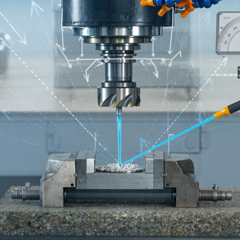
How to Improve Stability in High Speed Cutting?

Define the Stability Challenges in High-Speed Cutting

How to Improve Stability in High Speed Cutting?

Define the Stability Challenges in High-Speed Cutting

High-speed cutting is not automatically stable. The main challenge is regenerative chatter, caused by vibration marks repeating between tool passes. A 2022 review in CIRP Journal of Manufacturing Science and Technology identifies chatter as a major limit on surface quality, tool life, and material removal rate. Stability depends on spindle speed, axial depth, radial engagement, tool overhang, and workpiece stiffness. Small changes matter.

Start with measured evidence, not assumptions. Use impact testing to identify the tool-holder-spindle system’s natural frequencies. Then compare the results with stability-lobe calculations. Research published by the International Journal of Machine Tools and Manufacture shows that stability-lobe methods can locate deeper stable cutting zones than fixed speed testing. The improvement is often reported in the 20–40% range, but results vary with tooling and material. Do not treat that range as guaranteed.

Keep the tool overhang short. Check runout at the cutting edge, not only at the holder. A 10-micrometre runout can overload one tooth and create uneven forces. ISO 230-3 also reminds engineers to consider thermal behavior during machine evaluation. Heat can shift spindle conditions during long cuts. Perfect stability is rare. I would recheck the setup after tool changes, coolant changes, and workholding adjustments. A stable trial can become unstable by afternoon.

Select the Right Machine, Tool, and Workpiece Setup

How to Improve Stability in High Speed Cutting?

Select the Right Machine, Tool, and Workpiece Setup

High speed cutting begins with a rigid, responsive machine. Check spindle runout, bearing condition, and axis backlash before increasing speed. A flexible machine can turn a small vibration into visible chatter marks. Keep acceleration smooth, especially during tight corners and rapid tool changes. Cutting data should match the machine’s real condition, not only its catalog rating.

Tool selection needs equal care. Use a short tool whenever possible, because every extra millimeter increases deflection. A balanced holder and low runout improve surface quality and tool life. Choose a tool geometry suited to the material and avoid excessive radial engagement. In many shop trials, reducing engagement works better than simply lowering spindle speed. That detail is easy to miss.

Workpiece setup is often underestimated. Clamp near the cutting zone, but leave enough access for chip evacuation. Thin walls may need temporary support or a different machining sequence. I once saw a stable setup fail after the workpiece shifted slightly under heat. The fixture looked secure. It was not. Recheck contact surfaces, clamp pressure, and fastener condition before testing. Make a short trial cut, inspect the sound, chips, and surface, then adjust one variable at a time. This method feels slower, but it reveals the real cause of instability.

Optimize Cutting Parameters for Controlled Material Removal

How to Improve Stability in High Speed Cutting?

Optimize Cutting Parameters for Controlled Material Removal

High-speed cutting becomes unstable when the tool removes more material than the system can support. Controlled material removal begins with balanced cutting parameters. Set spindle speed according to tool diameter, material, and tool condition. Then adjust feed per tooth to maintain a steady chip load.

Use the equation: feed rate equals spindle speed multiplied by tooth count and feed per tooth.

Keep radial engagement modest during initial trials. A smaller engagement reduces cutting forces and limits sudden deflection. Small changes matter. Increase axial depth only after vibration remains controlled.

Before cutting, inspect tool runout and workholding stiffness. Even slight runout can overload one cutting edge. I check the tool holder, fixture contact, and machine sound during dry movement. If chatter appears, reduce axial depth or radial engagement before changing speed. Do not increase feed blindly. In one trial, lowering radial engagement by 20 percent produced a cleaner surface and steadier sound, although cycle time increased. That trade-off was acceptable for the part.

Record speed, feed per tooth, depth of cut, engagement, and observed vibration. These notes create reliable process evidence instead of relying on memory. Thermal changes can also shift stability during long cycles. A parameter that works in the morning may need adjustment later. Recheck the cut after tool wear, fixture changes, or material variation.

Reduce Vibration Through Rigidity, Balance, and Toolpath Design

How to Improve Stability in High Speed Cutting?

Reduce Vibration Through Rigidity, Balance, and Toolpath Design

High speed cutting becomes unstable when the tool, holder, spindle, or workpiece flexes under load. I check the entire setup before changing cutting parameters. A short tool overhang improves rigidity and reduces bending at the cutting edge. Clamping should hold the workpiece firmly without distorting thin sections. It sounds obvious. Small gaps still cause chatter.

Tool balance matters more as rotational speed increases. I inspect the holder, tool, and collet for damage, dirt, or uneven seating. Even a minor imbalance can create a repeating vibration through the spindle. Use the shortest practical assembly and verify runout with a reliable gauge. I once blamed the cutting speed for poor results. The real problem was tool seating. That diagnosis was incomplete.

Toolpath design can lower sudden changes in cutting force. Smooth entry moves, consistent engagement, and reduced corner acceleration often produce a cleaner sound and surface. Avoid forcing the tool into deep corners. Adaptive paths may help, but they still need suitable radial engagement. I compare spindle load, sound, and surface marks after each adjustment. This creates useful evidence instead of relying on one visual inspection. Sometimes a slightly slower feed produces better stability, even when productivity appears lower. A stable process protects the tool and makes dimensional results more repeatable.

Monitor Cutting Results and Refine the Process Systematically

How to Improve Stability in High Speed Cutting?

Monitor Cutting Results and Refine the Process Systematically

High speed cutting becomes unstable when small changes go unnoticed. I record spindle speed, feed rate, cutting depth, coolant flow, and spindle load for every trial. This simple log reveals patterns that memory often misses. A sharp tool should produce consistent chips, a controlled sound, and a clean surface. Sudden vibration, chipped edges, or changing chip color requires attention. Measure the workpiece after machining, not only by appearance. Dimensional drift can expose instability before it becomes a serious defect.

Change one variable at a time. For example, keep the toolpath and cutting depth fixed while adjusting feed rate by a small percentage. Then compare surface roughness, cycle time, tool wear, and spindle load. Repeat the test under similar material and temperature conditions. Results are not always perfect. I sometimes blame cutting speed when tool runout is the real cause. That mistake is useful, if it leads to better inspection. Check tool holding, workholding stiffness, and machine setup before increasing parameters.

Tips: Listen closely. A sharp, repeating tone may indicate chatter. Use a vibration sensor when available, but do not ignore direct observation. Inspect the tool under magnification after each controlled run. Keep successful settings with material, tool diameter, and engagement details. Avoid copying old parameters blindly. Cutting conditions change with tool wear, clamping pressure, and machine temperature. A stable process is built through measured adjustments, honest records, and repeated verification.

How to Improve Stability in High Speed Cutting? - Monitor Cutting Results and Refine the Process Systematically
Trial Workpiece Material Tool Diameter
(mm)
Spindle Speed
(rpm)
Cutting Speed
(m/min)
Feed Rate
(mm/min)
Axial DOC
(mm)
Radial DOC
(mm)
Peak Vibration
(g)
Surface Roughness Ra
(µm)
Flank Wear VB
(mm)
Stability Result Process Refinement
1 7075-T6 aluminum 10 12,000 377 1,200 8 1.0 0.18 1.42 0.03 Stable Baseline condition; no visible chatter marks.
2 7075-T6 aluminum 10 16,000 503 1,600 8 1.0 0.21 1.28 0.04 Stable Improved finish with a moderate increase in cutting speed.
3 7075-T6 aluminum 10 20,000 628 2,000 8 1.0 0.26 1.16 0.05 Stable Best measured finish; vibration remained below the alert limit.
4 7075-T6 aluminum 10 24,000 754 2,400 8 1.0 0.47 2.31 0.08 Unstable Chatter marks appeared; reduce radial engagement or change the spindle speed.
5 7075-T6 aluminum 10 18,000 565 1,800 8 0.7 0.19 1.21 0.05 Stable Reduced radial engagement to increase stiffness and suppress chatter.
6 7075-T6 aluminum 10 20,000 628 2,000 10 0.7 0.24 1.38 0.06 Stable Increased axial depth while retaining the lower radial engagement.
7 7075-T6 aluminum 10 20,000 628 2,400 10 0.7 0.34 1.76 0.07 Monitor Feed increase raised vibration; maintain the previous feed for finishing.
8 7075-T6 aluminum 10 19,000 597 1,900 10 0.7 0.20 1.19 0.05 Stable Selected as the working condition for consistent finish and low vibration.
Measurement basis: two-flute carbide end mill, air blast cooling, 7075-T6 aluminum, and a rigid machining setup. Cutting speed is calculated from tool diameter and spindle speed. Vibration and surface roughness values are recorded after a consistent trial pass; limits should be validated for the specific machine, tool, workholding method, and material.

FAQS

How can machine condition affect high-speed cutting stability?

Check spindle runout, bearing condition, axis backlash, and acceleration before increasing speed. A flexible machine can create chatter marks quickly. Match cutting data to the machine’s actual condition, not its catalog rating.

Why should cutting tools be short and balanced?

Short tools reduce deflection because every extra millimeter adds bending risk. Use a balanced holder with low runout. These details can improve surface quality and tool life.

How should the workpiece be clamped for stable cutting?

Clamp close to the cutting zone while leaving space for chip evacuation. Support thin walls when necessary. Recheck contact surfaces, clamp pressure, and fasteners before testing. The fixture may look secure. It may not be.

Which cutting parameters should be adjusted during initial trials?

Set spindle speed using tool diameter, material, and tool condition. Adjust feed per tooth for a steady chip load. Keep radial engagement modest at the beginning. Increase axial depth only after vibration remains controlled.

What should you do when chatter appears during machining?

Reduce axial depth or radial engagement before changing spindle speed. Do not increase feed blindly. In one trial, reducing engagement by 20 percent improved the surface and sound. Cycle time increased. That trade-off was acceptable.

How is feed rate calculated for milling?

Feed rate equals spindle speed multiplied by tooth count and feed per tooth. Use the equation carefully. A wrong tooth count can produce an unstable chip load.

What signs show that the cutting process is becoming unstable?

Watch for sudden vibration, chipped edges, changing chip color, or dimensional drift. A sharp, repeating tone may indicate chatter. Measure the workpiece, not only the surface appearance. Listen closely.

How can operators refine cutting conditions systematically?

Record speed, feed per tooth, cutting depth, engagement, coolant flow, and vibration. Change one variable at a time. Compare surface roughness, cycle time, tool wear, and spindle load. I sometimes blame cutting speed when tool runout is the real cause. That mistake is useful when it improves inspection.

Conclusion

How to improve stability in high-speed cutting begins with understanding the main sources of instability, including excessive vibration, poor machine rigidity, tool deflection, unbalanced rotating components, and unsuitable workpiece support. A stable process requires a well-matched machine, cutting tool, holder, and workpiece setup. Each component should provide sufficient stiffness and reliable clamping to prevent unwanted movement during machining.

Cutting parameters should be selected to control material removal without overloading the tool or machine. Spindle speed, feed rate, axial depth, and radial engagement must be adjusted according to the material, tool geometry, and machining operation. Stability can be further improved through balanced tooling, shorter tool overhang, appropriate coolant use, and toolpaths that maintain consistent cutting engagement. Finally, operators should monitor surface finish, cutting sound, tool wear, and machine behavior, then refine one parameter at a time. This systematic approach helps identify the real cause of instability and supports repeatable, efficient, and precise high-speed cutting.

Aria

Aria

Aria is a dedicated marketing professional with a deep passion for innovative strategies and a keen understanding of our company's product offerings. With a wealth of experience in the industry, Aria excels at crafting engaging content that highlights the unique features and benefits of our......